
P18 · I.06(c) · Tools · Industrial · Casing design framework
Casing design framework — VME, seats, CSE, worked verification
From API TR 5C3 uniaxial limits through the Von Mises ellipse, industrial Design Limit Plot, kick-tolerance seat selection and worked verification, then CwD, SET, GRE and connection envelopes. Design factors stay constant; applied loads get more severe.
CASING-DESIGN-FRAMEWORK-2026 · rev.16C · Excel Limit Check v6H · 4 September 2026 · François Dorléans · partner comments locked
Partner review (protected): each section has a #tag. Comments blocked for the public until ?role=partner.
Contents
- 1. Introduction and scope
- 2. Hierarchical schema of technical subjects
- 3. Sequential progression of the design process
- 4. Classical design basis (API TR 5C3)
- 5. Triaxial design — Von Mises ellipse
- 6. Industrial Design Limit Plot
- 7. Generic software load-case catalogue
- 8. Design factors remain constant
- 9. Casing While Drilling — increased load cases
- 10. Solid Expandable Tubulars
- 11. GRE specific constraints
- 12. Material selection and PREN
- 13. Custom loads that must be superimposed
- 14. Connection limits on the Design Limit Plot
- 15. Preliminary casing design — seat selection
- 16. Worked method: top-down, bottom-up and kick tolerance
- 17. Casing shoe depth: reasons other than kick tolerance
- 18. Detailed casing design — load-case principles
- 19. Worked example: uniaxial burst and collapse pipe selection
- 20. Cementing axial load, thermal and ballooning forces
- 21. Triaxial burst and biaxial collapse verification
- 22. Safety-factor formulas and plastic-collapse factors
- 23. Corrosion, wear and fatigue
- 24. Contingency and operational philosophy
- 25. Visualisation and supporting tools
- 26. List of references
- 27. Definition of acronyms
2. Hierarchical schema of technical subjects
3. Sequential progression of the design process
4. Classical design basis (API TR 5C3)
5. Triaxial design — Von Mises ellipse
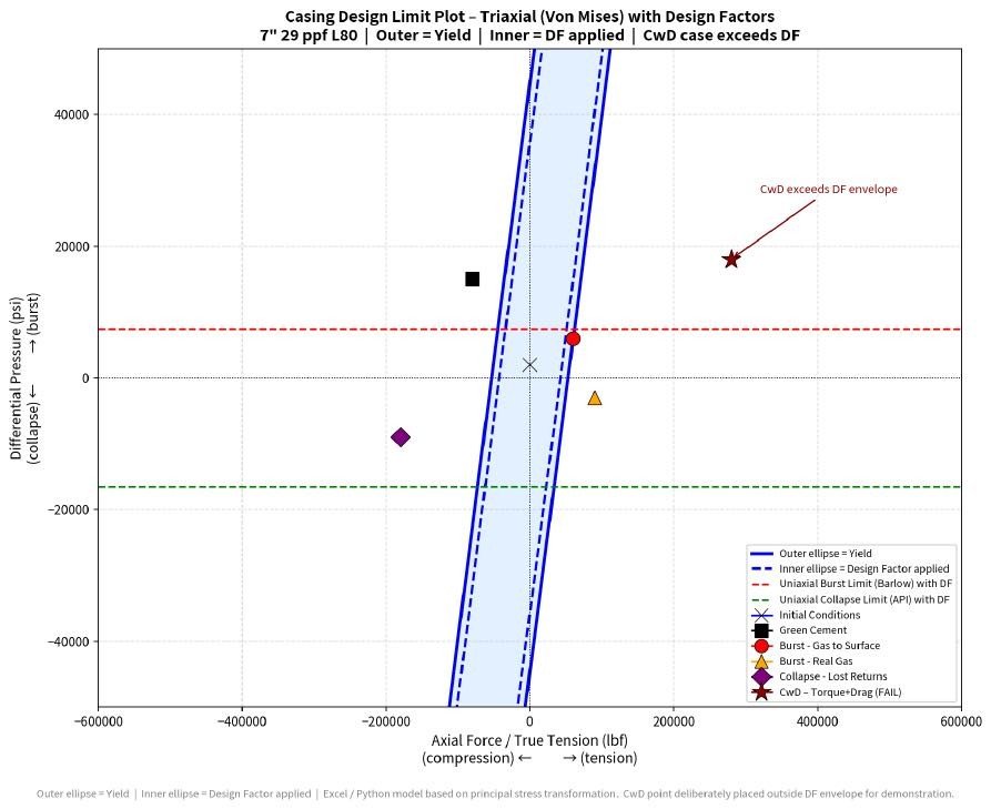
6. Industrial Design Limit Plot
7. Generic software load-case catalogue
8. Design factors remain constant
9. Casing While Drilling — increased load cases
10. Solid Expandable Tubulars
11. GRE specific constraints
12. Material selection and PREN
13. Custom loads that must be superimposed
14. Connection limits on the Design Limit Plot
15. Preliminary casing design — seat selection
16. Worked method: top-down, bottom-up and kick tolerance
17. Casing shoe depth: reasons other than kick tolerance
18. Detailed casing design — load-case principles
19. Worked example: uniaxial burst and collapse pipe selection
| OD (in) | Name | Hole (in) | Shoe MD (ft) | Shoe TVD (ft) | Mud at shoe (ppg) |
|---|---|---|---|---|---|
| 30 | Conductor | 36 | 690 | 690 | 8.6 |
| 18-5/8 | Surface casing | 24 | 1,280 | 1,280 | 8.75 |
| 13-3/8 | Intermediate casing | 16 | 9,200 | 7,745.6 | 10.3 |
| 9-5/8 | Production casing | 12-1/4 | 16,200 | 12,695.3 | 10.8 |
| 7 | Production liner | 8-1/2 | 19,200 | 14,816.6 | 11.8 |
20. Cementing axial load, thermal and ballooning forces
21. Triaxial burst and biaxial collapse verification
22. Safety-factor formulas and plastic-collapse factors
| Grade | A | B | C |
|---|---|---|---|
| K-55 | 2.991 | 0.0541 | 1,206 |
| L-80 | 3.071 | 0.0667 | 1,955 |
| C-90 / X-95 | 3.124 | 0.0743 | 2,404 |
| G-105 | 3.162 | 0.0794 | 2,702 |
| P-110 | 3.181 | 0.0819 | 2,852 |
| Q-125 | 3.239 | 0.0895 | 3,301 |
| S-135 | 3.278 | 0.0946 | 3,601 |
23. Corrosion, wear and fatigue
24. Contingency and operational philosophy
25. Visualisation and supporting tools
26. List of references
27. Definition of acronyms
Base dossier · PDF rev.16C Excel v6H Present · DFKPS I.06(a) I.06(b)